
This passive beamforming topology is not well known but is widely used — a common situation in the RF world.
For many years, radar applications defined much of the world of directional antennas. These antennas were designed with a fixed directivity or rotated in a steady pattern at a known rate, as seen in Figure 1. There were also antennas that could be re-positioned as needed, such as the huge ones used for radio astronomy. However, antennas with directivity that could be changed dynamically were unusual except for costly electronically steered antennas (ESA) primarily used for military radar systems.
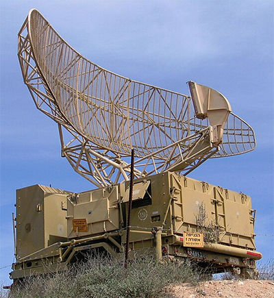
Figure 1. This mobile radar antenna is mechanically steerable but only in a limited, pre-defined pattern. (Image: Wikipedia)
In recent decades, however, this situation has changed dramatically. Antennas that can be redirected “on the fly” in real-time have become more common, driven by mass-market consumer products such as smartphones and their base stations. These applications need an antenna system that can not only change its directional focus as needed but does so much faster than any mechanically steered system.
The electronically steered antenna (ESA), also called a phased-array or multiple-input/multiple-output (MIMO) antenna, is now seeing widespread adoption. This FAQ will look at the Butler matrix, a widely used passive technique for implanting and ESA, which is not well known. This contradiction is not unusual, as the RF signal-processing world and its engineers have many unique and often mystifying devices and arrangements unfamiliar to the broader electronic engineering world.
Basics of electronically steered antennas
Q: What is the principle of electronic steering of an antenna’s directivity?
A: The principle has been well known since the early days of wireless and optics. By using a linear or two-dimensional array of antenna elements and precisely controlling the relative phase of the same signal driving each element, the phases of electromagnetic energy being transmitted or received see constructive and destructive interference at different angles.
Q: How is this electronic steering achieved?
A: Implementing electronic steering is a complex process, especially when the signal frequencies are in the hundreds of megahertz and tens of gigahertz, where the usual RF considerations and issues play a large role. There are two basic ways to provide this ability to dynamically adjust and control the phasing of the signal, called beamforming, to the antenna elements: active and passive.
Q: What is active beamforming?
A: An active beamforming network is constructed with power combiners/dividers, digitally controlled phase shifters, and attenuators. This type of network can offer continuous beam sweeping while the phase shifters and attenuators support broad bandwidth.
However, there are inevitable drawbacks that come with this technology. The digitally controlled phase shifters and attenuators require complex control circuitry, including digital-to-analog converters (DACs), analog-to-digital converters (ADCs), and logic-control circuits. The entire arrangement also requires considerable power. Effective heat dissipation and temperature-compensation circuits are required to maintain stable circuit performance.
The Bulter matrix is an alternative
Q: What is an alternative to active steering?
A: The Butler matrix, which is a passive beamforming network. It is configured in a n × n N × N square with hybrid couplers and fixed-value phase shifters at the internal junctions. The device has n N input ports (the beam ports) to which power is applied and N n output ports (the antenna elements) to which n antenna elements are connected.
The Butler matrix feeds power to the configured elements, so there is a progression of phase differences between elements; the result is that the beam of radio transmission is in the desired direction. The signal injected into one of the input connectors is distributed in equal amounts to all output connectors with very specific phase relations.
Q: Thus far, the discussion has focused on Butler matrices for transmitting, but can they be used for receiving?
A: Yes, the Butler matrix is a passive reciprocal network, so it works the same when it transmits energy as when it receives energy. They have the benefit that in transmit mode, they deliver the full power of the transmitter to the beam, and in receive mode, they collect signals from each of the beam directions with the full gain of the antenna array. For convenience, we’ll assume in our discussion that it is used as
Q: What is the size of the Butler matrix?
A: All Butler matrices have equal input and output ports. This number is always a power of two, from as low as 2 to 4, 8, 16, and higher. If fewer ports are needed, the unused ports must be terminated with matched loads or unwanted reflections will be back into the circuitry that severely distort the performance. The 64 × 64 size is widely used in aircraft scanning for scanning; some fixed installations even go to 128 × 128.
Matrix principles are not obvious
Q: How does the Butler matrix work?
A: Start with the smallest Butler matrix, which has just two inputs and two outputs, shown in Figure 2. An injected signal into Port 1 is split into two signals at ideally -3 dB amplitude and with quadrature phase, while injecting a signal into Port 2 yields the same output but with a mirrored phase. As a result, it can feed a two-element antenna array and generate one beam steered to the left and one beam steered to the right, depending on the choice of feed port.
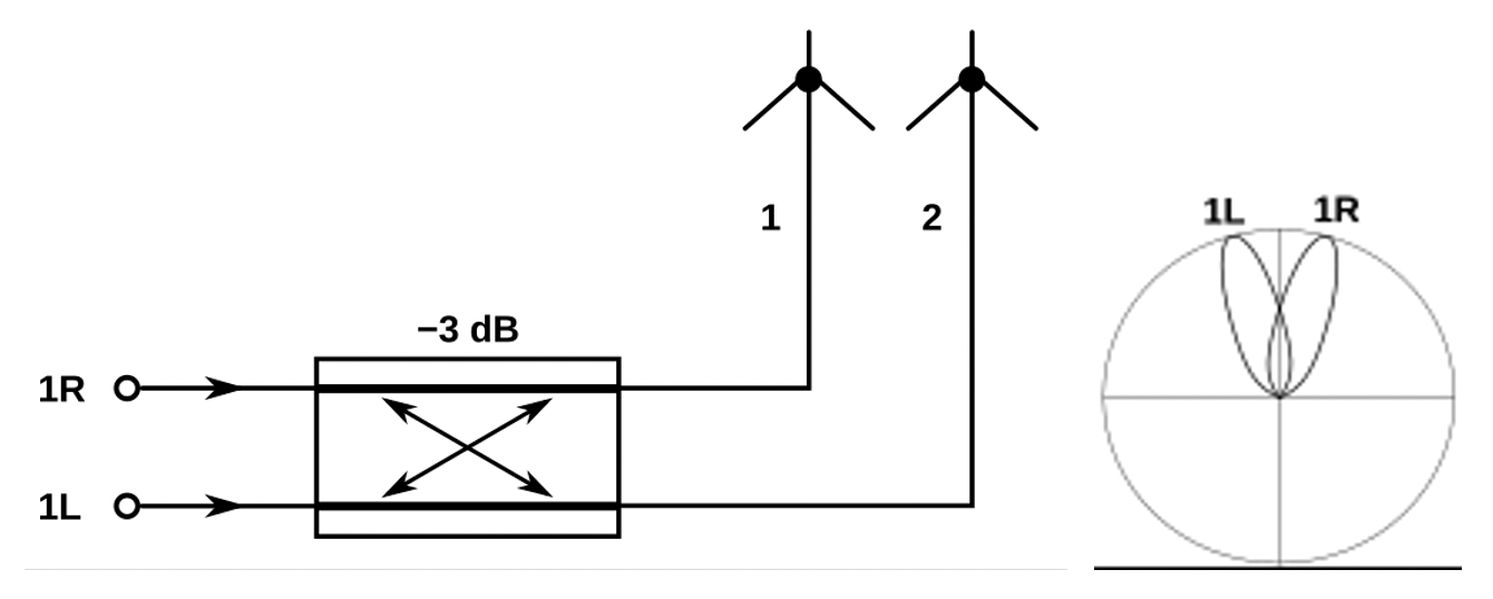
Figure 2. A 2 × 2 Butler matrix can cause the directivity of an antenna to skew off-axis either to the left or right. (Image: Wikipedia)
Note that the actual angular spread is a function of antenna element spacing, frequency, and other factors.
Q: What about for higher-order matrices?
A: The second-smallest Butler matrix has four inputs and four outputs, as seen in Figure 3. A signal injected into Port 1 is at -6 dB in each output with a progressive phase shift of 45°. For inputs 2, 3, and 4, the phase shifts are 135°, 225° and 315°, respectively. For phase angles, 225° is the same as -135° and 315° is the same as -45°. This generates two beams to the left and two to the right from the center-path “boresight.”
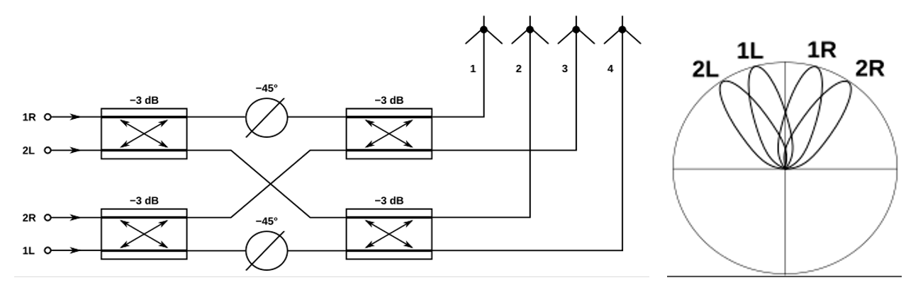
Figure 3. A 4 × 4 Butler matrix offers more granularity in the off-axis directivity. (Image: Wikipedia)
For the Butler matrices of even-higher order, such as 8 (seen in Figure 4), 16, and 32, the signal is split up with successively lower amplitudes of -9 dB, -12 dB, and -15 dB, respectively, with successively smaller progressive phase shifts of 22.5°, 11.25°, 5.625° and so on. The number of beams generated is always the same as the order of the Butler matrix, x, and their directions get denser as the order increases.
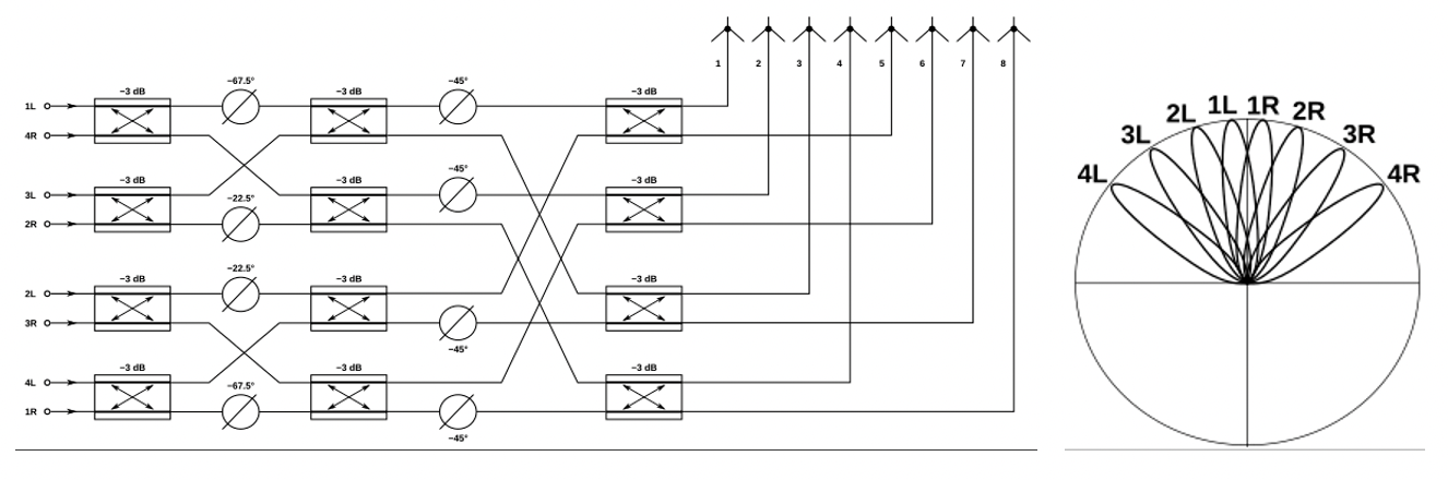
Figure 4. An 8 × 8 Butler matrix has even more granularity in the off-axis directivity but at a significant increase in hardware complexity and component count. (Image: Wikipedia)
Q: What is the relationship between the input port to which the signal is applied and the output port pattern?
A: The phase table below (Figure 5) for a 4 × 4 Butler matrix clarifies the relationship.
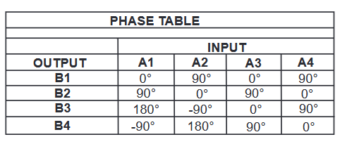
Figure 5. This input/output table for a 4 × 4 Butler matrix shows the relationship between the input port, which is fed a signal (A1 through A4), and the relative phasing of the outputs (B1 through B4). (Image: Krytar)
Q: Looking at the diagram, it appears that the phase shifters are the critical elements — are they?
A: In the RF world, every element is critical. The 2 × 2-port Butler matrix uses no phase shifters except for the 90° hybrid. The 4 × 4 matrix uses two 45° phase shifters in addition to the four hybrids. They are positioned in between the hybrid levels. The 8 × 8 matrix uses 22.5° and 67.5° between the first and second level and 45° phase shifters between the second and the third level. Higher-order matrices use successively finer phase shifts.
The absolute performance, tolerance, and stability of these phase shifters are critical factors in overall performance.
Q: I know what a phase shifter is, but please remind me: what is a “hybrid” in this context? I see the word used in so many ways.
A: Here, “hybrid” is short for “hybrid coupler.” A hybrid coupler is a special case of a directional coupler that divides an input signal evenly between two output ports with 3-dB coupling. The output signals can have a phase difference of 90 degrees or 180 degrees, depending on the design.
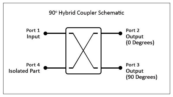
Figure 6. The basic hybrid coupler divides the input into an in-phase and a quadrature signal. (Image: EverythingRF)
Specifically, the 90° hybrid coupler is a passive 4-port, bidirectional device used to equally split an input signal into two signals, with a 90° phase shift (quadrature) between the ports, as shown in Figure 6. A signal at the input port (port 1) is divided between the two output ports, with half the power flowing to the 0° port and the other half flowing to the 90° port. Any reflection from mismatches at the output port flow to the Isolated port (port 4). For a 180° hybrid, the signal at port 3 is 180°.
Note that hybrid couplers can also be used in the reverse direction, combining two signals with 90° or 180° phase difference into a single signal.
The next part continues the exploration of this fascinating topology.
References
The Butler Matrix and its Use for Beamforming and MIMO Testing, Everything RF, EverythingRF
Butler Matrix, Microwaves101
Butler Matrix, Wikipedia
Butler Matrices and RF Switches, Spectrum Control
Wideband Butler Matrices and Their Potential Applications, MIcable
Butler Matrix KBM9010180, Krytar
Related EE World Online content
Creating 5G massive MIMO: Part 1
Creating massive MIMO, part 2
How many types of radar are there?
Module simulates 8×8 MIMO for 5G testing
Difference between a waveguide and transmission line
VSWR and impedance, Part 6: Microstrip and stripline