
In rotating machinery, shaft stiffness is often treated as an inherently desirable property: a stiffer shaft deflects less and keeps critical speeds above the operating range. Yet, many high-speed compressors, turbines, pumps, generators, and turboexpanders run successfully with flexible rotors that first pass through one or more bending critical speeds.
Flexibility is therefore not a weakness in itself. When controlled, it enables lighter, more compact, higher-speed machines; but when overlooked, it brings excessive vibration, high bearing loads, seal rubs, and thin stability margins. In this blog, we’ll explore when flexibility helps, when it hurts, and how AxSTREAM RotorDynamics & Bearing lets engineers evaluate the complete rotor-bearing system.
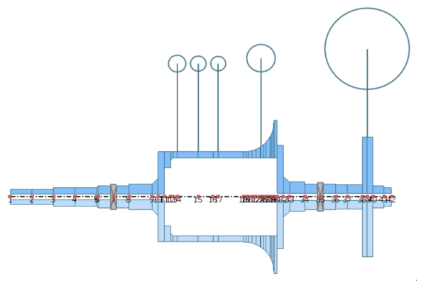
Figure 1. Rotor model of a gas turbine engine, a typical flexible-rotor machine, built in AxSTREAM RotorDynamics
What Makes a Rotor Flexible?
Geometry alone does not decide whether a rotor is considered flexible. Disks and impellers, bearings, seals, supports, mass distribution, speed, and gyroscopic effects all contribute, so the same shaft can be stiff in one machine and flexible in another.
What matters is how the rotor behaves during operation. A rotor is considered flexible when shaft bending becomes dynamically significant within or near its operating-speed range, particularly when it approaches or passes through a bending critical speed during startup. Many flexible rotors have several bending modes, each excited at a different critical speed.
That’s why maximizing shaft stiffness isn’t necessarily the goal. Increasing shaft diameter can raise bending frequencies, but it also adds mass, increases bearing and seal surface speeds, and may shift other vibration modes into the operating-speed range. The aim is to control critical speeds, mode shapes, damping, and response, turning flexibility from a risk to manage into an advantage.
When Flexibility Becomes an Advantage
A flexible-rotor design offers real benefits in several situations:
| Where flexibility helps | The benefit |
|---|---|
| High-speed operation | The rotor passes safely through its first bending critical speed and runs in a stable range above it. |
| Lower mass and compact packaging | A smaller shaft diameter suits lightweight or space-constrained machines, if strength, fatigue, thermal, and torque limits are met. |
| Critical-speed placement | A resonance can be put in a startup or shutdown region the machine crosses quickly, rather than inside continuous operation. |
| Mode-shape control | Bearing locations, shaft geometry, and mass distribution can be tuned so peak shaft motion falls away from seals and tight clearances. |
These benefits can be seen in Figure 2, which shows the unbalance response of a gas turbine engine that runs above its first two critical speeds.
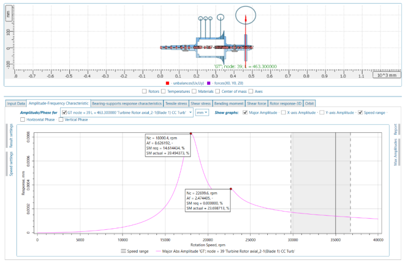
Figure 2. Unbalance response of a gas turbine engine operating above its first two critical speeds, with amplification factor and separation margin for each, calculated in AxSTREAM RotorDynamics
A critical speed does not always have to be eliminated. With enough damping and little time near resonance, crossing it during acceleration is acceptable. The amplification factor (AF) measures how strongly vibration is magnified as the rotor passes through a critical speed. It is read from the unbalance response curve as the critical speed divided by the width of the resonance peak at 0.707 of its maximum amplitude, so a sharp, lightly damped peak has a high AF, while a broad, well-damped peak has a low one. API 684 gives the criteria – a resonance with an AF of 2.5 or higher counts as a critical speed needing a separation margin from the operating range; a lower AF is damped enough to be treated as non-critical. In Figure 2, the first peak has an AF near 8.6, requiring about a 15 percent margin, which this design meets with almost 40 percent. In plain terms, the rotor passes through a sharp resonance during startup, but at operating speed it runs far enough away that unbalance produces only low vibration. The resonance still exists – it is simply placed where the machine spends almost no time, which is how flexibility becomes an advantage.
When Flexibility Becomes a Liability
When left unevaluated, that same flexibility can create serious problems:
| Where flexibility hurts | What can go wrong |
|---|---|
| Critical speeds near continuous operation | Synchronous unbalance drives high vibration when a bending resonance sits inside or too close to the operating range. |
| Excessive internal motion | Shaft displacement between the bearings can be large even when housing vibration looks moderate, risking seal rubs, clearance loss, and rotor-to-stator contact. |
| Sensitivity to unbalance | Response depends on where residual unbalance sits relative to each mode shape, so flexible rotors often need multiplane or modal balancing. |
| Dependence on bearings and supports | Stiffness, damping, clearance, preload, lubricant condition, and foundation flexibility all shift critical speeds and mode shapes. |
| Reduced stability margin | Bearings, seals, and aerodynamic effects add cross-coupled forces that feed energy into whirl and produce subsynchronous vibration. |
Because of these risks, modal analysis alone is insufficient. Damped unbalance-response analysis gives vibration amplitudes and bearing reactions, and high-speed machines also need damped eigenvalue analysis for the logarithmic decrement – API 684 treats 0.1 as the minimum acceptable value on the first forward-whirl mode. The logarithmic decrement measures how quickly a free vibration dies out from one cycle to the next: positive means stable, and higher means more damping in reserve. Below 0.1, the rotor is not considered stable enough for reliable operation.
The Role of Bearings and Supports
Bearings do more than carry static rotor weight as their dynamic stiffness and damping shape the natural frequencies, mode shapes, response, and stability of the whole machine. Housings, pedestals, and foundations should not be assumed rigid either.
Raising bearing stiffness lifts some critical speeds, but not linearly. Once a mode is dominated by shaft bending, stiffer supports add little, and they transmit less damping into the rotor, which is exactly what it needs when crossing a resonance.
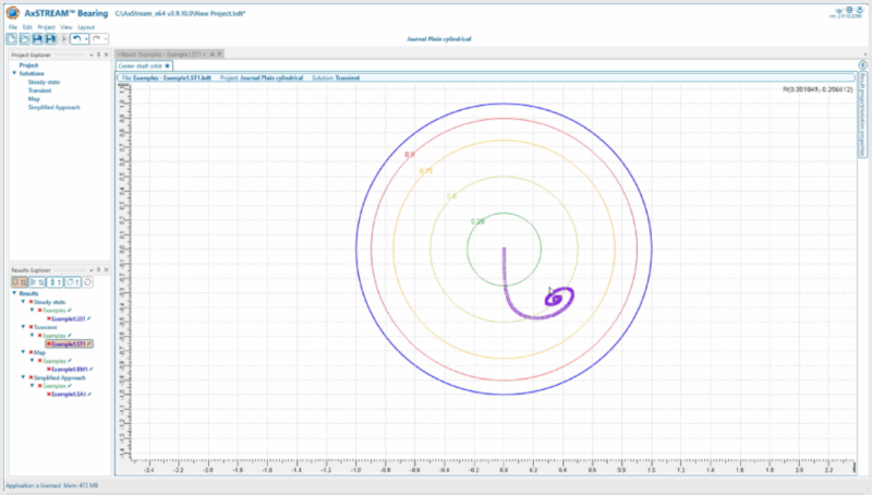
Figure 3. Transient response of the shaft center within the bearing circle, calculated in AxSTREAM Bearing
That trade-off is why squeeze film dampers are common in high-speed rotors. Installed in series with a bearing, a damper adds damping with minimal additional stiffness, reducing peak vibration amplitude and the amplification factor at bending critical speeds while limiting the dynamic loads transmitted to the housing. Because factors such as clearance and oil supply significantly influence damper performance, AxSTREAM Bearing calculates speed-dependent bearing and damper coefficients that can be incorporated directly into the rotordynamic model.
Evaluating Flexible Rotors with AxSTREAM RotorDynamics & Bearing
Modern rotordynamic analysis lets engineers compare concepts before hardware is fixed. AxSTREAM RotorDynamics represents the shaft as a distributed flexible structure with disks, impellers, bearings, seals, couplings, supports, and applied loads.
From one model, engineers can calculate critical speeds and mode shapes, generate critical-speed maps and Campbell diagrams, evaluate the logarithmic decrement, predict unbalance response with amplification factors and separation margins, and run sensitivity studies on shaft, bearing, damper, and support parameters.
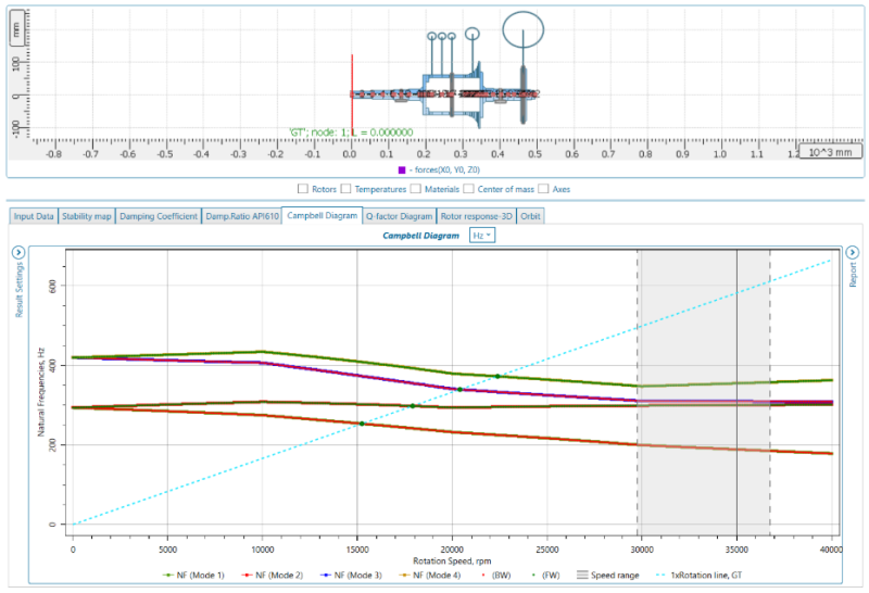
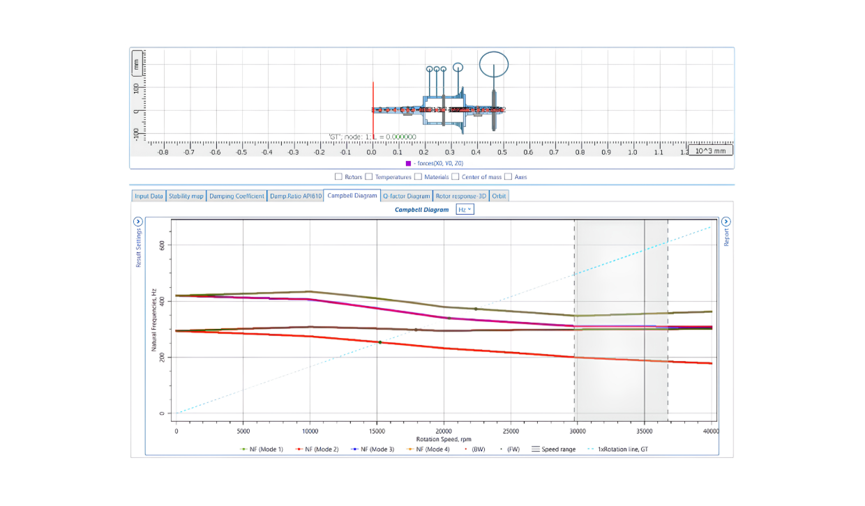
Figure 4. Campbell diagram of a gas turbine engine showing the critical speeds crossed below the operating speed range, calculated in AxSTREAM RotorDynamics
Designing Flexibility, Not Just Minimizing It
Shaft flexibility is neither automatically good nor bad, and the goal is not maximum rigidity. The machines that gain the most from flexibility are the ones designed for it: by controlling critical speeds and mode shapes, providing enough damping, and verifying vibration, bearing loads, clearances, and stability against defined criteria before hardware is built. With AxSTREAM RotorDynamics & Bearing, flexibility becomes a deliberate design choice rather than an unexpected liability.
References
- E. J. Gunter, Introduction to Rotor Dynamics: Critical Speed and Unbalance Response Analysis, RODYN Vibration Analysis, 2001.
- American Petroleum Institute, API RP 684, Rotordynamic Tutorial, 2nd ed. Washington, D.C.: API Publishing Services, 2005.
- J. M. Vance, F. J. Zeidan, and B. G. Murphy, Machinery Vibration and Rotordynamics. Hoboken, NJ: John Wiley & Sons, 2010.