
By Bjorn Fehrm and Henry Tam.
November 28, 2025, ©. Leeham News: We do a series about ideas on how the long development times for large airliners can be shortened. New projects talk about cutting development time and reaching certification and production faster than previous projects.
The series will discuss the typical development cycles for an FAA Part 25 aircraft, called a transport category aircraft, and what different ideas there are to reduce the development times.
We will use the Gantt plan in Figure 1 as a base for our discussions. We have exited the Detailed Design phase after conducting Critical Design Reviews, CDRs, and now enter into Prototype Manufacturing.
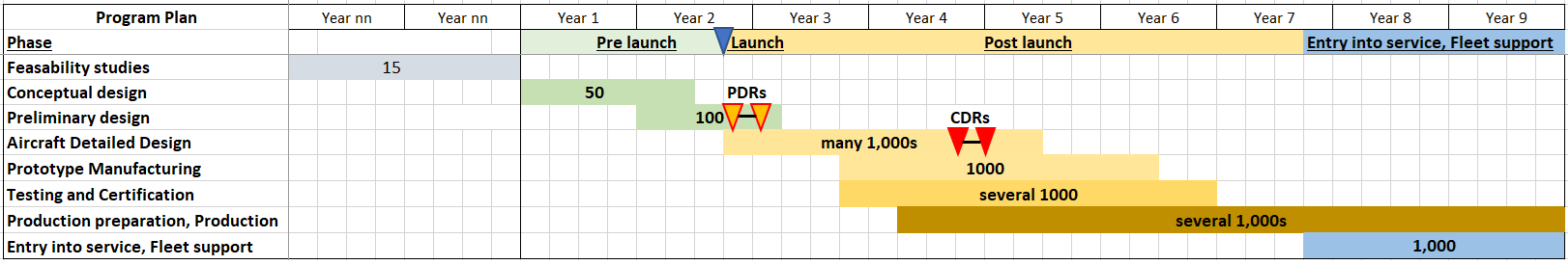
Figure 1. A generic new Part 25 airliner development plan. Source: Leeham Co. Click to see better.
** Special thanks to Ron Everlove for helping with this article **
Here are a couple of terms you will see in the following articles:
Designated Engineering Representative (DER) – In the United States, a DER is an individual who is appointed by the FAA to act on their behalf to approve or recommend approval of regulatory compliance and related technical data to the FAA. These individuals can be working as an independent consultant or an employee of the aircraft manufacturer. Aircraft manufacturers that have an Organization Designation Authorization (ODA) organization utilize these Unit Members, UMs, who operate in a similar manner to DERs. Please note that the title is different in other jurisdictions.
Designated Manufacturing Inspection Representative (DMIR) – A DMIR, in the US, is an individual who is appointed by the FAA to conduct conformity inspections during the manufacturing process. A DMIR must possess aeronautical knowledge and experience, be employed by a Production Approval Holder (PAH), or a PAH’s approved supplier, and meet the FAA’s qualification requirements.
Prototype Parts and Systems Manufacturing
Now that the program has completed all Critical Design Reviews and exited the Detailed Design phase, the team has to focus on getting parts for qualification tests, test rigs, and the flight test aircraft. The suppliers have started producing parts and preparing to ship them to the appropriate test and manufacturing sites.
First Article Inspection
First Article Inspection (FAI) is an important step when getting parts from a supplier. Engineering and quality teams send representatives to the supplier to inspect the first shipset against requirements and specifications. The process allows the supplier to demonstrate that the production setup, manufacturing process, tooling, etc., are capable of consistently meeting requirements and specifications. If a part fails the inspection, the supplier needs to rework the part and apply appropriate corrective actions to ensure future parts will meet requirements and specifications. Additional inspections may also be required depending on the situation.
Component/Part Qualification
As previously mentioned, parts need to go through qualification campaigns to generate compliance data to support aircraft certification. Qualification plans were already created and discussed with the authority during the last phase. The plan needs to be approved by the authority or their designee (DER/UM) before the qualification test begins. The step-by-step test procedure also needs to be reviewed and approved by the authority.
Let’s use a bleed air valve as an example. The supplier of the valve needs to demonstrate that the valve can operate and survive in a defined set of environmental conditions. The authority and the OEM agree to use specific chapters of the DO-160, Environmental Conditions and Test Procedures for Airborne Equipment, as qualification requirements and test procedures. These tests include, but are not limited to, temperature, altitude, humidity, vibration, and shock.
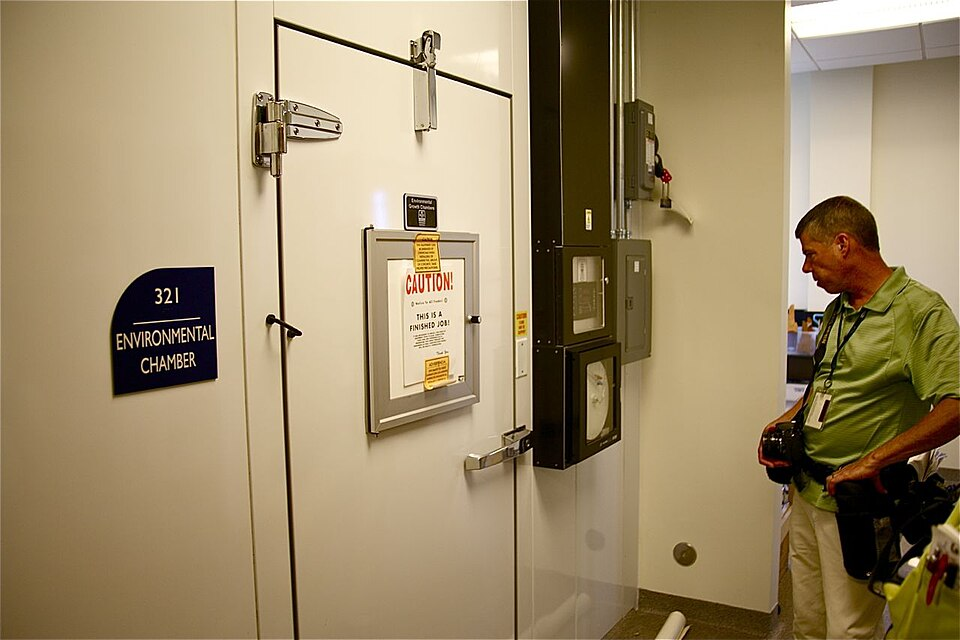
Figure 2. Environmental Chamber. Source: Wikipedia.
In addition, the bleed valve may be required to demonstrate that it is fireproof as well. To do so, the supplier needs to use approved test methods, such as those provided in FAA Advisory Circular (AC) 20-135, Powerplant Installation and Propulsion System Component Fire Protection Test Methods, Standards, and Criteria, to qualify the component as fireproof.
According to the Advisory Circular, this means that the capability of a material or component to withstand, as well as or better than steel, a 2000°F flame (±150°F) for 15 minutes minimum while still fulfilling its design purpose. The term “fireproof”, when applied to materials and parts used to confine fires within designated fire zones, means that the material or part will perform this function under conditions likely to occur in such zones and will withstand a 2000°F flame (±150°F) for 15 minutes minimum.
Related test equipment, test criteria, etc., are presented in this Advisory Circular. If a Type Certificate applicant wants to use other methods to show compliance, they need to negotiate with the authority and obtain approval for these methods.
Prior to a qualification test, authority-authorized personnel, such as a DMIR, need to conduct a conformity inspection. The purpose of the inspection is to ensure that test articles, installations, functions, and test setups conform to the FAA-approved design data. An OEM cannot use data from a test with nonconforming test articles or setups for compliance demonstrations.
When witnessing a test, an authority-authorized witness, such as a DER, needs to witness that test procedures are followed and that the instrumentation appears to provide valid data. A test report is then generated to document that the part meets the design requirements. This report will later be used to substantiate compliance with airworthiness standards.
System Level Tests
Suppliers also need to demonstrate that their systems can comply with the requirements. Let’s use the fuel system as an example. Here are a few rules related to fuel flow:
(a) Each fuel system must provide at least 100 percent of the fuel flow required under each intended operating condition and maneuver. Compliance must be shown as follows:
- Fuel must be delivered to each engine at a pressure within the limits specified in the engine type certificate.
- The quantity of fuel in the tank may not exceed the amount established as the unusable fuel supply for that tank under the requirements of § 25.959, plus that necessary to show compliance with this section.
- Each main pump must be used that is necessary for each operating condition and attitude for which compliance with this section is shown, and the appropriate emergency pump must be substituted for each main pump so used.
- If there is a fuel flowmeter, it must be blocked, and the fuel must flow through the meter or its bypass.
- If an engine can be supplied with fuel from more than one tank, the fuel system must:
- (1) For each reciprocating engine, supply the full fuel pressure to that engine in not more than 20 seconds after switching to any other fuel tank containing usable fuel when engine malfunctioning becomes apparent due to the depletion of the fuel supply in any tank from which the engine can be fed; and
- (2) For each turbine engine, in addition to having appropriate manual switching capability, be designed to prevent interruption of fuel flow to that engine, without attention by the flight crew, when any tank supplying fuel to that engine is depleted of usable fuel during normal operation, and any other tank, that normally supplies fuel to that engine alone, contains usable fuel.
In order to show compliance to these rules, the fuel system supplier may use a fuel system rig representative of our aircraft’s fuel system for tests. Similar to component qualification, the system test plan needs to be approved by the authority.
An authority-authorized personnel, such as a DMIR, needs to conduct a conformity inspection, and a DER must witness the test. A test report is then generated and can be used to show compliance with airworthiness standards. There is a potential to reduce the number of flight test cases if agreed by the authorities.
Next Article
We have now described some aspects of the parts and systems production and testing that precede the manufacturing of the first Prototype aircraft. In the next article, we look at putting together the first test aircraft.
Related