


Radomes are a critical part of the exposed wireless and RF world. Whether for fixed-in-place radar installations on aircraft fuselages or even for automotive safety radar, they have the challenge of being RF-transparent at the frequencies of interest while providing environmental protection against wind, rain, snow, and vehicle or aircraft motion.
Some radomes are primarily for protection, while others are for both protection and minimizing aerodynamic impact. The first radomes were developed during World War II, made of plexiglass to protect aircraft radar and other radio antennas in flight as well as minimize drag; some early radomes also used a fiberglass layer.
Radomes soon expanded to highly visible “golf ball” shapes made of rigid sections and could house a large dish and other antennas, as seen in Figure 1. Some smaller radomes were made of flexible fabric stretched over a frame, using pressurized air for rigidity.

Figure 1. The popular image of a radome is a large sphere that resembles a golf ball. (Image: Milexia Products)
There are also radomes made of specialty materials and shaped to blend invisibly into the structure of the vehicle, such as a car with radar (often at 77 GHz). All types of radomes are in use, and each has attributes that make it the appropriate choice in the target application.
This article will look at some of the material science and frequency-related RF issues that are associated with the development of a radome, called out in Figure 2. Many of the issues apply to radomes of all sizes, while some are more relevant to specific radome types.
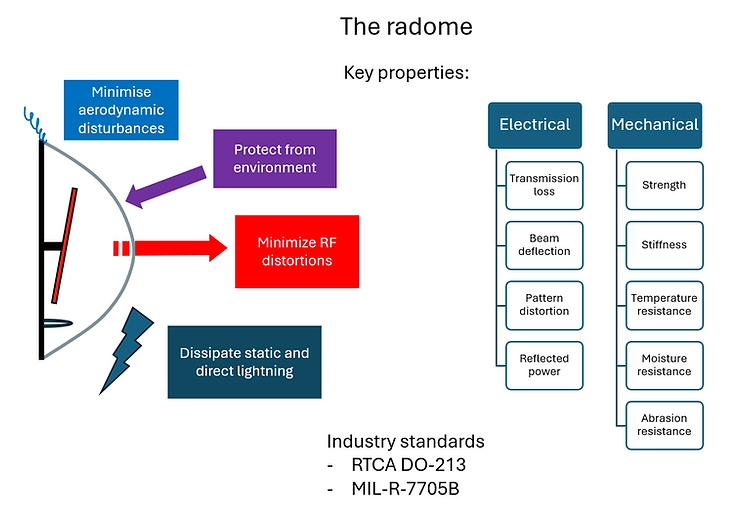
Figure 2. Despite its simple appearance, the radome actually has many technical requirements placed on it, along with electrical and mechanical constraints. (Image: The Engineering Pilot)
One thing is certain: while a radome looks like a simple piece of RF-transparent “plastic,” it is much more than that.
Note that the word radome is what linguists call a “portmanteau” word, a term coined by Lewis Carroll in Through the Looking Glass, where two words are combined to form a new word. “Radome” blends “radar” and “dome” and there are hundreds of such words in English, such as “smog” (“smoke and “fog”) or “brunch” (breakfast and lunch”). A portmanteau is different from an acronym, which uses main letters to make a new word, such as “radar,” which is derived from “Radio Detection And Ranging.”
Begin with electromagnetic reality
A radome is a solid material that is interposed between the antenna and its operating environment, which is usually outside in the open, but doesn’t have to be so. Depending on the material from which it is made, it may be visible or invisible to the eye while seemingly transparent to RF energy across its operating band.
The classic radome is often represented to non-technical audiences as a large, white structure that houses an antenna that is at least several meters across and is associated with military scanning units in harsh climates, or even weather radar for local TV stations.
That obvious golf-ball radome is only one of many in standard use. In recent decades, with the huge growth of cell towers and their top-mounted antennas, radomes have played a role as the covers of the small boxes housing the antenna, and sometimes the cell-site electronics have become commonplace. They also have a role in consumer products such as occupancy detectors and alarm systems. Note that the antenna and transmit/receive circuity in many of these smaller applications are collocated and mounted on a single board, and are called a “sensor” rather than an antenna, but for simplicity, we’ll use the designation antenna for all cases.
As a material interposed between the antenna and the outside, the radome ideally does not attenuate, distort, or phase shift the transmitted/received waveform. Radomes also follow the reciprocity rule: whatever applies to the propagation situation of the transmitted wave also applies to the received wave.
Materials and layers
There are some basic electromagnetic factors that are critical to an effective radome from an RF perspective, along with related material and mechanical issues, including the materials used and the thickness of the layer or layers of the radome material. It is nearly impossible to discuss electromagnetic waves and their propagation without the use of some equations, but we’ll keep those to a minimum here.
When an electromagnetic (EM) wave propagates and is incident at the interface between two dielectrics, such as plastic and air, both reflection and refraction occur at the boundary. The changes in propagation speed and wavelength within the dielectric are a function of the material’s permittivity. If the wavelength in free space is 𝜆0 (5 millimeters at 60 GHz), the wavelength inside the material is 𝜆 =𝜆0√𝜀𝑟, where 𝜀𝑟 is the relative dielectric constant of the material.
Materials with a higher dielectric constant produce stronger reflections of the incidence signal. Conductors, such as metals, have a very high dielectric constant (𝜀𝑟 →∞) and thus produce a strong reflection. In contrast, most polymers have a dielectric constant in a range between 2 and 4 and therefore give a weaker reflection.
As an incident wave hits the first interface, a reflection 𝑟1 and a transmission 𝑡1 occur, seen in Figure 3. Note that 𝑟12 and transmission 𝑡2 occur.
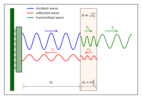
Figure 3. Analysis of the radome wall thickness begins with RF wavelength and wall-air interfaces in the context of incident, reflected, and transmitted waves. (Image: Acconeer AB)
The optimum radome thickness occurs when the dielectric is perfectly reflectionless, which occurs when the thickness is a multiple of half a wavelength. In that case, the round trip of the wave inside the radome introduces a 360° phase shift, thereby canceling the reflected wave 𝑟1.
As an example, if the material is polycarbonate with relative permittivity 𝜀𝑟 = 2.75, the optimal radome thickness becomes:
d2 = 𝑚 × (𝜆/2) = 𝑚 × (𝜆0/2√𝜀𝑟) = 𝑚 × 5/(2√2.75) ≈ 𝑚 × 1.51 mm, for 𝑚=1, 2,… (higher order reflections)
If the dielectric thickness is an odd multiple of 𝜆/4, maximum reflection occurs, which is very undesirable.
The material properties that make the most difference are those that make a signal susceptible to loss: dielectric constant (Dk) and loss tangent/dissipation factor (Df). Dielectric constant represents a material’s ability to store energy, while loss tangent refers to energy loss due to physical properties. It is important to keep these values as low as possible to minimize signal loss in radome material selection.
The next part looks at some geometry issues and how they affect radome design and performance.
Filed Under: Communications, Featured, Radar, RF