

Timing holdover keeps a system’s clock accurate after it loses its outside timing reference. It can last for seconds, hours, or even days. Telecom networks, radar systems, and satellite constellations all depend on it the moment that reference disappears. Without holdover, these systems lose the shared clock that keeps them in sync.
In this FAQ, we examine what happens inside an oscillator during holdover, why it is mission-critical for defense radar systems, and how satellite constellations hold synchronization on their own.
The role of the oscillator during holdover
A holdover capable timing system normally uses a phase-locked loop (PLL) to keep its output frequency locked to an outside reference. The PLL constantly compares the reference to its own output. It then adjusts a digitally controlled oscillator (DCO) to correct any difference. This feedback loop is what keeps a whole network of clocks agreeing with each other.
The outside reference can disappear at any time. This might happen from a lost global navigation satellite system (GNSS) or from a network fault. Once that happens, the PLL has nothing left to compare against. A holdover circuit does not let the DCO drift freely at this point. Instead, it freezes the DCO’s control input at the last known good value. From there, the oscillator runs on its own accuracy alone.
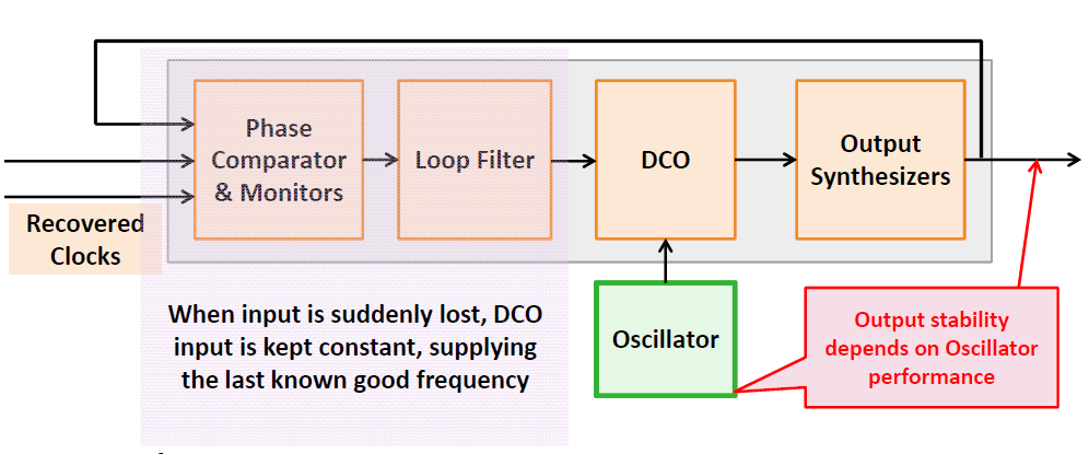
Figure 1. A simple block diagram demonstrating the operation of timing holdover operation. (Image: Workshop on Synchronization and Timing Systems)
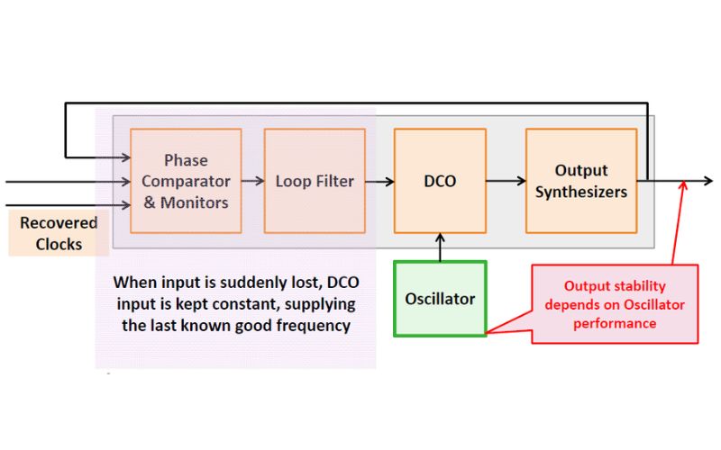
As Figure 1 shows, the PLL holds the DCO’s control input steady the instant the reference input disappears. In this case, the output stability depends entirely on the oscillator. As a typical example, initial holdover frequency runs around ±50 ppb under best-case conditions, with an initial phase jump of about 120 ns as the loop transitions into holdover.
Two mechanisms account for most of the ongoing drift once handover begins. Oscillator temperature stability contributes roughly ±2 ppm across a typical -40°C to +85°C range, while aging alone adds about ±100 ppb of drift for every 24 hours the oscillator runs without correction.
Mission-critical defense and aerospace systems usually replace those numbers with an oven-controlled crystal oscillator (OCXO) or a rubidium standard, which maintains stability several orders of magnitude tighter. Even so, the same two mechanisms still set a ceiling. Temperature sensitivity and aging limit how long any oscillator class can run unassisted before its timing error becomes unacceptable.
Why does holdover matter for defense radar systems?
Multistatic radar systems synchronize transmit and receive nodes at different locations to a shared time and frequency reference. GNSS-disciplined oscillators (GNSSDOs) normally hold that reference so the nodes’ returns can combine at a central processor. Adversaries can jam or spoof GNSS to deny it, but they are often limited to a few nodes. The affected nodes then depend on holdover to keep combining data reliably.

Figure 2 compares the carrier phase of two radar nodes, each disciplined to its own GNSSDOs, during two 30-second loop-back trials at a 2.42 GHz carrier frequency. One node’s transmission was split and fed back to itself and to the second node to simulate a fixed target. This ensured that the oscillator’s phase behavior was isolated from any real target motion.
The two nodes’ carrier phases drifted closely enough to confirm coherence between them. That correlation confirms that local oscillator phase error propagates directly into radar phase error.
A separate 900-second GNSS-denial test on the same system showed real bistatic range error growing from 13.3 m to 29.9 m as the oscillators drifted apart in holdover. That growth degrades the radar’s ability to resolve and track a target. The key engineering lesson for us to understand is that holdover performance depends more on the frequency offset between oscillators at the moment of loss than on the oscillator’s own datasheet stability rating.
Why does holdover matter for satellite constellations in low Earth orbit?
Equipping every low-earth orbit (LEO) satellite in a constellation of thousands with an onboard atomic clock is not realistic, given the cost, mass, and power involved. GNSS carries its own risk, since jamming or spoofing can deny the signal. Adding to it, the ground station contact only covers about seven minutes of a satellite’s roughly 100-minute orbit.
The alternative is a high-stability crystal oscillator that estimates and corrects for temperature and aging drift in real time. Each satellite recalibrates during that brief contact window, then holds its own time autonomously until the next one.
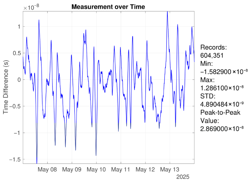
Figure 3 shows the results from a ground-based hardware validation platform. Note that this is not an in-orbit satellite. The setup used a physical crystal oscillator guided by a GNSS receiver’s 1PPS signal. It cycles through the same brief ground-contact pattern a real constellation would see. Held that way, timing deviation stayed better than 30 ns peak-to-peak over a full week of testing.
The underlying method itself introduces 4.93 ns of error, at one standard deviation, from ground testing only. An actual in-orbit deployment would add link-calibration uncertainty and orbit, geometric, and atmospheric delay terms. But autonomous holdover is still what makes constellation-scale deployment feasible without an atomic clock on every spacecraft.
Summary
When designing systems that should take care of reference outages, do not rely on the oscillator’s datasheet stability rating alone. As the radar data above show, the frequency offset between oscillators at the moment of loss often matters more than the oscillator’s own rated stability.
For mission-critical defense or aerospace designs, spend the extra cost and power on a better oscillator, such as an OCXO or a rubidium standard. Treat the ground test numbers here, like the LEO result, as a best case. A real satellite in orbit adds more error on top of that, due to link calibration drift and orbital geometry.
References
High-Precision Time Synchronization and Autonomous Maintenance for LEO Satellite Constellations Based on High-Stability Crystal Oscillators, Sensors. MDPI
Global Navigation Satellite Systems disciplined oscillator synchronisation of multistatic radar, IET Radar, Sonar & Navigation
Time Holdover and Oscillator Requirements, Workshop on Synchronization and Timing Systems
EEWorld Online related content
Phase Locked Loop: A fundamental building block in wireless technology
The PC-board atomic clock, Part 1: Primary and secondary standards
Quartz crystals and oscillators, Part 1: Crystal basics
GPS is a ubiquitous and problematic technology
eLORAN a terrestrial alternative to GPS
Keeping hackers out of GPS receivers
Filed Under: Communications, Featured


