
Achieving the design point, or Best Efficiency Point (BEP), is one of the key objectives in centrifugal pump design. At BEP, the pump operates with the highest hydraulic efficiency, minimum internal losses, and the most stable flow pattern through the impeller and casing. When the actual operating point moves away from BEP, the flow angles no longer match the blade geometry. This can lead to separation, recirculation, increased turbulence, pressure pulsations, vibration, and higher hydraulic loads. As a result, the pump may fail to deliver its expected performance, consume more power, and have reduced reliability and service life.
In this blog, we’ll cover the most common reasons pumps fail to reach their design point, how to address them, and how modern tools like AxSTREAM can help during the design process.
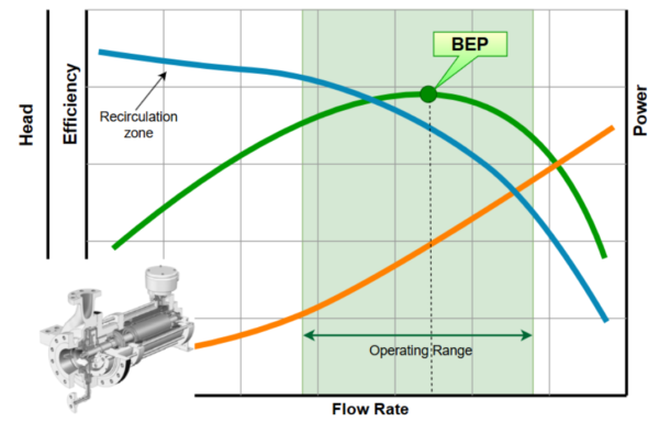
Figure 1. Pump performance curves and BEP
What are the Common Hydraulic Pump Design Problems?
Performance deviations may come from both hydraulic design assumptions and practical implementation factors. The differences between the flow field simplifications required during concept design and the physical complexity of the actual flow field often causes performance predictions to deviate from real-world results. Therfore, identifying the sources of deviation is essential for understanding whether the problem is caused by the impeller, casing, loss prediction, CFD assumptions, manufacturing accuracy, or the selected operating range.
Common hydraulic design problems usually arise when the impeller geometry, internal loss prediction, and casing geometry are treated separately rather than as one coupled hydraulic system. The main consequences include insufficient head, reduced efficiency, increased power demand, higher net positive suction head required (NPSHr), pressure pulsations, and vibration.
1. Impeller design.
Impeller-related design errors are among the most common reasons a centrifugal pump fails to reach its expected design point. At the preliminary design stage, the inlet and outlet diameters, channel width, blade inlet and outlet metal angles, number of blades, and overall passage shape must be selected consistently with the required flow rate, head, and rotational speed. If these parameters fall outside the recommended ranges, the incoming flow may not match the blade geometry. This increases incidence losses, separation, recirculation, slip, cavitation risk, and ultimately reduces pump efficiency and head.
A reliable impeller design normally starts with the correct selection of specific speed, which defines the suitable pump type and gives the first indication of the required proportions of the flow path. AxSTREAM, simplifies this process. The user specifies the key operating parameters, such as flow rate, pump head, and shaft speed, while the specific speed and main geometric relationships are calculated automatically during solution generation. This allows the designer to focus on defining practical engineering constraints instead of manually checking every possible geometry combination.
The Preliminary Design module in AxSTREAM [2] can generate a broad set of candidate impeller geometries based on the specified boundary conditions and parameter ranges. Along with the main duty point parameters, the designer can control important geometric and hydrodynamic variables, including flow factor, diameter ratio, meridional velocity gradient in the impeller, blade exit angle, channel width, and number of blades. The filtering system then makes it possible to remove solutions that don’t satisfy the required limits for geometry, performance, cavitation margin, or efficiency, leaving only the most suitable designs for further analysis.
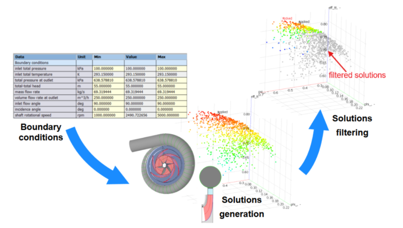
Figure 2. Fragments of the Preliminary Design module in AxSTREAM
2. Pump losses.
Another challenge in pump design is accurately estimating and evaluating hydraulic and mechanical losses. Total pump losses include impeller passage friction, incidence losses, diffusion losses, secondary-flow losses, volute losses, leakage through clearances, disk-friction losses, and losses caused by surface roughness. If these losses are underestimated, the predicted head and efficiency become overly optimistic, and the final pump may operate below the expected design point. Conversely, overly conservative loss assumptions can lead to an unnecessarily large or inefficient design. So, the loss balance should be realistic and consistent with the selected geometry and operating range.
When designing a pump and evaluating its losses, the selected loss models are a key consideration, because they directly influence the predicted performance curves, efficiency level, power consumption, and BEP location. AxSTREAM offers loss models [3] developed from technical literature, the internally developed data, published technical data, and models. These models can also be calibrated using available experimental data or previous project results. This calibration helps improve prediction accuracy and makes the preliminary design more reliable before moving to detailed CFD verification.
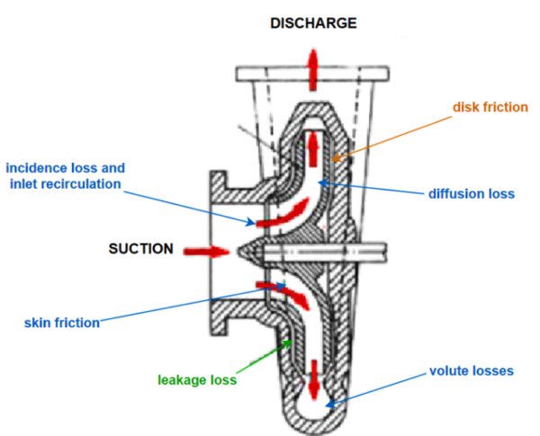
Figure 3. Hydraulic Pump losses
3. Poor impeller-volute interaction.
The flow leaving the impeller is non-uniform and interacts with the volute tongue, throat area, and circumferential pressure field. If the impeller outlet flow angle, velocity distribution, or flow rate does not match the volute geometry, the energy transfer from the impeller to the casing becomes less efficient. Poor matching can cause local separation near the tongue, pressure pulsations, increased radial thrust, vibration, noise, and a shift of the head and efficiency curves. These effects are usually more pronounced at off-design flow rates, where the circumferential pressure distribution becomes less balanced and the impeller experiences stronger unsteady loading.
To avoid these problems, it is recommended to design the impeller and the volute or diffuser together, checking the volute throat area, outlet width, and pressure recovery as part of one hydraulic system. CFD verification is especially useful at this stage because it helps identify local separation zones, high-loss regions, and unstable flow structures before the geometry is finalized.
4. Excessive internal leakage.
Large wear-ring, front-side, or rear-side clearances reduce the effective flow through the impeller and lower the pump’s overall efficiency. Part of the delivered flow returns through leakage paths instead of contributing to useful head generation, so the impeller must handle additional internal circulation. In some cases, leakage can also strengthen recirculation, disturb the inlet flow, increase disk-friction losses, and affect axial thrust balance. Underestimating leakage flow during pump design can be a crucial issue , because it can lead to an overprediction of volumetric efficiency and a mismatch between calculated and tested performance.
Therefore, clearance dimensions, seal geometry, and leakage paths should be checked together with the main flow path rather than treated as secondary details. AxSTREAM, can calculate leakage through the front and back seals [4], allows to adjust the dimensions of the seals and clearances, and optimize these parameters to improve the predicted performance and reduce unnecessary internal losses.
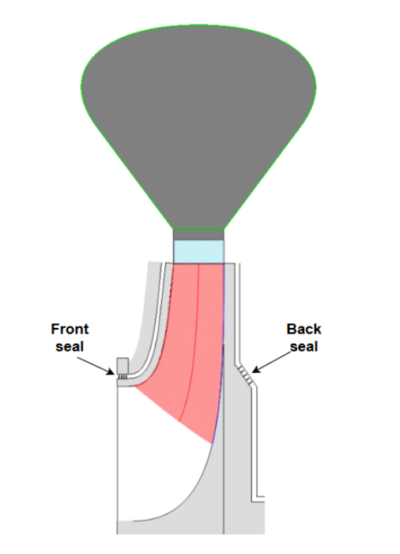
Figure 4. Leakages modelling in AxSTREAM
5. Cavitation.
Cavitation can occur when local pressure drops below vapor pressure due to excessive inlet velocity, unfavorable incidence, or insufficient net positive suction head available (NPSHa). If the cavitation margin is insufficient, cavitation develops in the pump flow passage and can degrade performance. Screw inducers can be used as an effective design approach to improve cavitation characteristics and are a type of axial-flow rotor characterized by high cavitation resistance. They are therefore frequently installed upstream of the main impeller to improve the cavitation performance of pumps.
Estimating NPSHa [5] and NPSHr [6, 9] during AxSTREAM Preliminary Design helps ensure that the selected impeller inlet geometry, leading-edge shape, and velocity distribution are compatible with the available suction conditions. This makes the final design more likely to meet the target head and efficiency while maintaining stable operation over the required flow range.
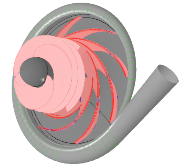
Figure 5. Centrifugal pump with screw inducer in AxSTREAM
6. Manufacturing deviations and surface roughness.
Even a well-constructed hydraulic design can produce an impeller that differs from its nominal geometry because of blade-angle deviations, thickness variation, passage-width errors, casting defects, or rough surfaces. These deviations change the actual flow passage, increase friction and local separation losses, and can reduce both head and efficiency. Therefore, manufacturing tolerances and surface finish should be considered during design verification rather than treated only as production issues.
7. Insufficient model verification.
A design may look acceptable when its checked only at one operating point or with an insufficient CFD setup. A coarse mesh, unsuitable boundary conditions, or inappropriate turbulence and cavitation models can hide local separation, recirculation, high-loss regions, and cavitation risk. For this reason, CFD verification of the geometry and flow patterns is an important step in pump design and optimization. It helps assess losses, cavitation characteristics, and three-dimensional flow effects in the curved channels of turbomachinery impellers.
AxSTREAM supports this process through its AxCFD solver [7], which covers the main stages of 3D CFD modeling, including mesh generation, preprocessing, case setup, solution monitoring, and postprocessing. In the latest AxSTREAM version, users can also run the Ansys CFX solver directly in AxCFD [8] together with the internal AxCFD solver.
How to Achieve Design Point in Hydraulic Pump Design
Achieving the required design point depends on consistently treating the pump as a complete hydraulic system rather than as a set of separate components. Impeller geometry, loss balance, leakage paths, cavitation margin, manufacturing tolerances, and impeller-volute interaction are closely connected, and any weakness in one of these areas can shift the head curve, reduce efficiency, increase power demand, or move the operating point away from the intended BEP.
A reliable design process should combine appropriate specific speed selection, realistic preliminary sizing, loss analysis, flow-path optimization, cavitation assessment, and CFD verification. These steps help confirm not only that the pump can reach the design point, but also that it can maintain stable and efficient operation over the required operating range.
AxSTREAM supports this design process by providing an effective workflow for generating suitable candidates, filtering them by performance and geometry limits, evaluating losses and cavitation characteristics, and verifying the final flow field before the pump geometry is finalized.
References:
Gülich J.F. Centrifugal pumps, Second edition, Springer-Verlag, Berlin: Heidelberg, 2010.
SoftInWay Inc., “Fan/Compressor/Pump Design”. [Online]. Available: https://wiki.softinway.com/v3.10.9/softinway-wiki/axstream-flow-path/axstream-positive-pressure-gradient-machine/fan-compressor-pump-design.md.
SoftInWay Inc., “Calculation Models”. [Online]. Available: https://wiki.softinway.com/v3.10.9/softinway-wiki/axstream-flow-path/axstream-positive-pressure-gradient-machine/nomenclature/calculation-models.md.
SoftInWay Inc., “Back Seal Leakage in Centrifugal Compressors and Pumps”. [Online]. Available: https://wiki.softinway.com/v3.10.9/softinway-wiki/axstream-flow-path/axstream-positive-pressure-gradient-machine/axstream-ppg-documentation/back-seal-leakage-in-CC-and-pumps.md.
SoftInWay Inc., “Net Positive Suction Head”. [Online]. Available: https://wiki.softinway.com/v3.10.9/softinway-wiki/axstream-flow-path/axstream-positive-pressure-gradient-machine/nomenclature/machine-parameters/net-positive-suction-head.md.
SoftInWay Inc., “Net Positive Suction Head Required”. [Online]. Available: https://wiki.softinway.com/v3.10.9/softinway-wiki/axstream-flow-path/axstream-positive-pressure-gradient-machine/nomenclature/machine-parameters/net-positive-suction-head-required.md.
SoftInWay Inc., “AxCFD Help”. [Online]. Available: https://wiki.softinway.com/v3.10.9/softinway-wiki/axcfd/axcfd-help.md.
SoftInWay Inc., “User Guide. Using the ANSYS CFX Solver within the AxSTREAM Integrated Environment”. [Online]. Available: https://wiki.softinway.com/v3.10.9/softinway-wiki/axcfd/axcfd-cfx.md.
Goldenberg V., Rublevskiy E., Zhang T., Sherbina A., Conser B. Cavitation Prediction and Avoidance in Design using Semi-Empirical 1D Models with Fast 3D CFD Validation. Proceedings of the 50th Turbomachinery & Pump Symposia, Houston, Texas, USA, 2021.