
Each of the three topologies of this versatile system building block has its place in modern systems.
The phase-locked loop (PLL) plays a vital role in many electronic systems and circuits. It has been used in various forms since the 1930s, providing diverse functions, all related to timing, clocking, frequency synthesis, synchronization, and signal recovery.
Note that it is called a phase-locked loop, yet many of the applications are centered on frequency rather than phase — so perhaps it should be called a frequency-locked loop, but that’s not the case. However, there is a close and intimate relationship between phase and frequency, as frequency is the time derivative of phase, just as acceleration is the time derivative of velocity.
Bolstering the “phase” nomenclature, from an operational perspective, the PLL really is a phase-driven device. Its operation is driven by a phase difference, while frequency requires looking over a longer time period. Phase is the instantaneous position along the continuum of a periodic signal, while frequency is continuing flow and timing. Thus, the term “phase” is more indicative of its operation.
This article will briefly review the original all-analog PLL and its successor, the digital PLL with some analog elements (often called a hybrid PLL). Finally, it will then look at the latest implementation for this critical function: the all-digital PLL (ADPLL).
It will not go into operational details as these are covered in countless articles, books, and more with perspectives ranging from qualitative overviews to intense modeling, analysis, equations, and considerations. It will briefly look at issues associated with the all-analog and hybrid PLLs. As one professor noted many years ago (sorry, I don’t recall the specific citation; I am paraphrasing from memory): “The PLL is the electric engineer’s equivalent to Shakespeare or James Joyce, as it has been the topic of countless graduate-level papers.”
For tangible evidence of the PLL’s longevity and importance, the seminal analysis of PLL operation, performance, error sources, and noise issues is the book “Phaselock Techniques” by Floyd M. Gardner, first published in 1966 and now in its third edition (2005). It’s unusual to see any academic analysis of PLLs that does not cite this work, even in the 2020s.
A brief history of PLLs
The first PLLs were built in the 1930s using vacuum-tube circuitry. Their primary application was to align and synchronize two analog carriers for demodulation of signals (“digital” data as we know it today did not exist yet). Given the complexities of the arrangement, the PLL was only used in high-end and classified military installations, as well as some long-distance broadcast radio links.
The development of the solid-state transistor simplified the construction of PLLs while reducing their cost, power needs, and size. Still, it was a special circuit to be used only if there was no alternative. However, there soon was a mass application when consumer analog-based color TV was introduced in the 1950s. Each TV set receiver included a special PLL design to synchronize the received color-subcarrier at 3.58 MHz to the internal crystal in the receiver (this analog TV standard served until it was declared obsolete in 2009).
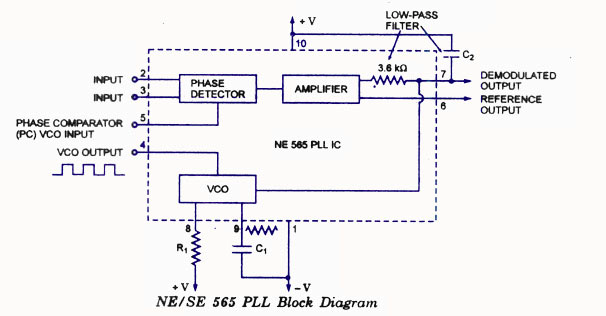
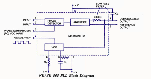
Along with the development of analog ICs, one PLL device stands out: the NE565 introduced in 1969 by Signetics Corp. (acquired by Philips Semiconductor in 1975, in turn, became part of NXP Semiconductors in 2006). This fully integrated, bipolar monolithic PLL IC of Figure 1 was available in a 14-pin DIP package and a 10-pin metal-can package.
It could operate up to about 500 kHz, making it suitable for many leading-edge applications in the audio and even low RF ranges. Due to its performance and subsequent popularity, it was second-sourced by many other manufacturers. While it has been obsolete for many years, it still shows up in hobbyist designs, and there are many “unofficial” sources for it still available.
Basic PLL operation (without equations)
As noted previously, there are many available descriptions of the PLL and explanations of its operation at various levels and with different technical intensities. While the basics are irrefutable, the details may differ in terminology or perspective, as users of PLLs for, say, reclocking, have a different frame of reference than those using PLLs for frequency synthesis.
Regardless of application, the basic PLL is a closed-loop feedback-control system, usually using some form of the proportional-integral (PI) loop strategy (PI is a subset of PID, which adds a derivative component not needed for PLLs). There are many setup and performance issues: response speed, overshoot, transient response, bandwidth, signal noise, jitter, phase noise, linearity, and more that additional analysis can reveal. The basic and more enhanced characterization of the PLL can be fairly intense, with complex control-loop equations providing desired insight (one of the reasons it is so popular with academics, no doubt!)
The analog PLL is made up of five key components, seen in Figure 2:
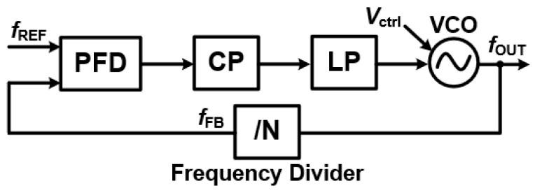
- Phase/Frequency Detector (PFD): This component acts as the “comparator.” It takes the input reference signal () and compares its phase and frequency with the feedback signal from the Voltage-Controlled Oscillator (VCO). The PFD then generates an error signal that is directly proportional to any difference between the two.
- Charge Pump (CP): The Charge Pump converts this error signal into a proportional current or voltage.
- Loop Filter (LF): This is a low-pass filter that takes the charge pump’s output and smooths out the signal by suppressing high-frequency noise, producing a stable control voltage ( ).
The filter is often a second-order passive-RC network, and the specifics of this loop filter are a major factor in determining PLL dynamic performance to meet the application needs and priorities.
- Voltage-Controlled Oscillator (VCO): The VCO generates the output signal ( ), and its frequency is directly controlled by the stable voltage from the Loop Filter. The relationship is often expressed as =0 + × , where 0 represents the VCO’s free-running frequency and is its gain.
- Frequency Divider (FD) (optional): In the feedback path, the Frequency Divider scales the VCO’s output frequency down to match the reference frequency. Depending on the design of this block, it allows for both integer-N and fractional-N division, providing flexibility in frequency generation.
The frequency divider – a digital function in almost all cases — was a relatively late addition to the PLL design. Many PLL applications, such as clock recovery and synchronization, do not need the divider; it is needed for frequency synthesis.
In early PLLs, the filter was an external, user-supplied block. In later ICs, it was incorporated into the IC, but in most designs, the user could still set the filter parameters via resistors and capacitors to meet the application priorities.
Another important point about the filter is this: while designers strive to implement the best phase/frequency detector, charge pump, voltage-controlled oscillator, and other elements possible with respect to absolute performance, the situation of the filter is different. The reason is that there is no “best” filter; rather, there are myriad choices in filter specifics, and these have a major role in determining the performance of the PLL loop.
The next part of this article looks at the mostly digital PLL and the all-digital versions, along with some other issues.
References
TUTORIAL: Phase Locked Loops, Integrated Device Technology, Inc.
ECEN620: Network Theory, Broadband Circuit Design, Texas A&M University
A Design Procedure for All-Digital Phase-Locked Loops Based on a Charge-Pump Phase-Locked-Loop Analogy, IEEE Transaction on Circuits and Systems
An Overview of Phase-Locked Loop: From Fundamentals to the Frontier, National Library of Medicine
Types of PLL in VLSI: Analog, Digital, and All-Digital PLLs, Success Bridge
Digitally controlled oscillator, Wikipedia
Three Major PLL Implementations, Movellus
Phase-Locked Loop (PLL) Fundamentals, Analog Devices
Signetics SE/NE 565 PLL Overview, Scribd
The Phase Locked Loop IC as a Communication System Building Block, Texas Instruments
Lecture 080 – All Digital Phase Lock Loops (ADPLL), Georgia Institute of Technology
Related EEWorld Online content
What is Proportional (PID) Control and why is it used? (Part 1)
What is Proportional (PID) Control and why is it used? (Part 2)
RCA & Color TV: A dominant company and standard, both now gone – Part 2
Does 32 kHz or 3.58 MHz mean anything to you? part 2
Synthesized tuning, Part 1: Basic frequency-synthesizer principles
Synthesized tuning, Part 2: Advanced synthesizers and performance
Filed Under: Communications, FAQ, Featured