
by Bruno Damien, Ecosystem Marketing Director at e-peas.
Most IoT devices still rely on a disposable battery, and that battery is often the weakest link in the design. It drives recurring cost, whether that means a consumer replacing a coin cell or a facilities team truck-rolling to service sensors across multiple sites.
The EU estimates that millions – and potentially tens of millions — of batteries from IoT devices are discarded every day, despite all required measures taken to ease collection of such toxic waste. And legislation/positioning papers aimed at OEMs is already being drafted to address it. Energy harvesting removes the battery dependency, but it changes the power architecture. Here’s how to design for it.
A typical IoT system comprises a sensor or actuator, coupled with a low-power MCU, data transmission, and supporting elements such as memory, crystal oscillators for clocking, security features, and, of course, power.
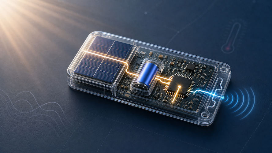
Switching from disposable batteries to energy harvesting requires only limited changes, with the energy harvesting element of the design bringing in three specific components: the harvester; an energy store; and a PMIC, as seen in Figure 1.

And recent years have seen several advances in each of these. Improvements in solar technologies, PMICs and MPPT tracking algorithms have enhanced conversion efficiency. Advances in the materials science of energy stores have increased their power density and recyclability. Flexible/ultra-thin capacitors and PV cells are also enabling new form factors that no longer have to work around, for example, a triple-A battery compartment. This all makes it easier to make the switch.
And while each project may be different, the process of implementing a design requires just six standard steps and in the below we’ll examine these.
Step 1 — Assess the variable power budget
Energy harvesting is not limited to just low-power systems, with the storage element and harvester size being able to increase to enable use in higher-power applications.
The first step is therefore to undertake a power budget analysis, calculating both the average and peak power demands. This can be used to determine what storage and harvester size is needed from the load, or to define power constraints ahead of development. Understanding the energy budget of any application can be done manually, but more recently tools such as SiLabs Simplicity Studio Energy Profiler, Nordic Semiconductor’s NRF-PPK2, Qoitec’s Otii and Undalogic’s mini SMUs have hugely simplified the task.
Note, with IoT devices needing to run for years off a coin cell or similar, they seem to be highly optimized for efficiency. While this is a good start, it’s still wise to undertake a review of each component to check for possible efficiency gains before switching to energy harvesting designs. There are plenty of unexpected behaviours to be corrected and simple path for improvements showing as low-hanging fruits.
Step 2 — Select the optimal energy source
IoT and consumer devices will often be well suited to small photovoltaic cell arrays, but thermoelectric generators and piezoelectric transducers are also available.
PV cells can be implemented for both outdoor (bright or cloud-covered sunlight) use and indoor (LED lighting) with the latest generation of PV cells and PMICs even able to transition between the two.
Thermoelectric generators can be really well suited to smart home systems, where there is a reliable temperature gradient. Or for use on moving machinery, piezoelectric generators may represent the best option. Other examples include kinetic switches – which can be ideally suited to wireless light switches – giving enough energy when (and only when) it’s needed.
For optimal extraction, various MPPT algorithms will need to be implemented, but today, advanced PMICs for energy harvesting will undertake this directly.
Step 3 — Select the storage
Energy from harvesters can be directed not only to the application, but to storage, with two main categories: chemical (batteries) and electrostatic (capacitors), with a hybrid (lithium capacitors) also available.
The choice requires a good understanding of product capabilities. Supercapacitors are far easier to recycle and exhibit extremely good endurance in charge / discharge cycling and temperature swings, whereas batteries have a higher energy density, and sodium-ion types tend to reduce the eco-toxicity.
The overdischarge threshold should also be considered, with supercapacitors able to go down to zero vs rechargeable batteries and lithium capacitors having an overdischarge threshold of around 3 V typical.
Of course, the choice and specifics of storage will also be dictated by (or will influence) the specified ambient energy source, with the source voltage needing to be distinct from the storage voltage range. For supercapacitors, which go down to 0 V, the source voltage must always be higher than the capacitor range.
Introducing a margin of >0.3 V is good practice, and will, as exemplified in Figure 2, ensure the boost converter can always provide the necessary voltage for charging.

Step 4 — Determine the supply voltage and current range
For any application powered by energy harvesting, it’s vital to understand the minimum, maximum and optimal supply voltages for the application circuit. It’s also vital to confirm if a regulated output is needed, as this will affect the PMIC and ripple voltage.
For supply current, one needs to understand both the maximum peak and idle-mode currents.
Step 5 — Select the PMIC
In an energy-harvesting system, the PMIC optimizes interactions with the source and connects the energy storage system and the main supply for powering the load. It also handles the monitoring and control circuitry to enable cold-start and wake-up as well as cell balancing and storage element protection – preventing overcharging / deep discharging, as well as overheating when needed.
As such, optional functions include supercapacitor cell balancing, storage element thermal protection, average power monitoring and a 5 V charger capability.
A wide range of options exist, with PMICs created for specific energy source types, power ranges, storage types, etc. There are also dual-source PMICs to allow, for example, PV with TEG, as well as ones with high dynamic ranges that can cope with the full output range of the latest indoor-outdoor PV cells.
Step 6 — Prototype
Finally, with a growing ecosystem of interconnected partners, the industry is making it easier to prototype using evaluation boards. This includes the ability to test not only different energy sources, storage technologies and PMICs, but also to vary the MCU, data transmission protocols and other on-board components.
The payoff extends beyond design simplicity. Studies have shown that switching from disposable batteries to energy harvesting for IoT device power can lower OPEX for facility managers by up to and beyond 80%, and TCO by between 30% and 50% depending on the use case. Others have demonstrated sustainable products can be sold at a substantial premium for both B2C and B2B systems.
About the author
Bruno Damien is the Ecosystem Marketing Director at e-peas, a leading developer of power management ICs and MCUs for energy harvesting applications.
Filed Under: Communications, Featured